A Homemade 5m ASW-28
A lavishly detailed article on this unique, FES-equipped glider intended for mountain flying and GPS triangle racing.
While this article appears under my byline I must emphasise the text was co-authored with Jean-Luc Foucher and the beautiful pictures were a collaboration with Frédéric Hours. My deepest thanks to them for their participation in the creation of this article. — PR
Introduction
Iam taking my pen today to tell you about a nice project led by two longtime friends, Frédéric Hours and Joël Carlin who are both F3F competition pilots. This project was born three years ago and the first flight — I was lucky enough to attend — was made at the end of May 2020, at the end of the first lockdown. But let’s not rush the steps and let’s start by talking a little about the genesis of this glider.
A Simple Yet Ambitious Idea
The initial idea was to design and build a large, electrified F3F glider with a 5m wingspan and a semi-scale look. Intended for slope and mountain flying and eventually a little GPS triangle racing (GPSTR), it will be equipped with a motor in the nose — a front electric self-launch (FES) system. While being discrete it will enable going up in case of weak air. This is a key point in my opinion if you want to fully enjoy this kind of glider without risking it. Elevation in the mountains is sometimes important and it is not rare to go down low and fast without necessarily having the possibility of landing safely. The motor is beneficial as it allows to push the search for the lift a little further or a little longer.
The wings will be built from a vacuum laminated core while the fuselage would be constructed using an existing homemade mold, to be determined later in the process.
It remained to define which model specifically. The type of construction of the wings imposed a multi-panel wing requirement. Joel and Frédéric reviewed the different models on the RC glider market such as the Diana 2, or the AN66 GPSTR type or the large gliders such as the ASG-29 and ASW-27 for which it is quite easy to find a 1/3-scale mold. The choice was quickly made for the ASW-28 in its 15m version. It offers the possibility of a wing with a reasonable aspect ratio of 19.5 while also allowing the use of a thin airfoil. It also employed the geometry of trapezoids to approach an elliptical lift distribution while remaining close to the wing shape of the full-size glider. Note however that the model has six wide chord control surfaces and not just ailerons and airbrakes as found on the full-size aircraft.

Once the geometry of the wing was defined, our two friends called upon Jean-Luc Foucher — the father of the Alliaj HM, but also of the Prodij HM by Aeromod, the Pingouin F3F and the Cosmos F3F — to design the airfoils of this new 5m glider. Jean-Luc accepted the challenge and what better way than to tell us about it himself, so I’ll pass him the pen.
Aerodynamics (Jean-Luc Foucher)
Aerodynamics is just an exciting hobby for me and is treated as any other physics topic. I employ my experience in fluid dynamics related to various topics such as: F3F, dynamic soaring, 3D helicopter blades, racers and windfoils. By experience we address three main phases: objectives/constraints, flight mechanics/specs and airfoil computation.

Objectives and Constraints
The first objective is to achieve an ‘F3F-like’ behavior. This means maneuverability, acceleration, turn efficiency and a wide range of speed. This also means a speed range from 15m/s to 50m/s, and the highest turn Cl/Cd ratio. The second objective is to increase the overall soaring capability compared to F3F. One constraint is to have very ‘friendly’ behavior with no hard stall so that it can be used by non-expert pilots. The second constraint is to keep the ASW-28 shape leading to an airfoil chord (from 77mm to 308mm), mass range from 9kg to 13kg and wing area of 117dm². And finally, the third constraint is to have at least 11% of airfoil thickness at the wing root for mechanical strength.
Flight Mechanics and Technical Specifications
For this purpose general aerodynamic equations are used: one output is that airfoils along the wingspan will have to be analyzed over a wide Re range — from 1e5 to 1e6. Another output is a Cl range between 0 and around 0.7 all over Re range. For soaring we have to focus on Cl up to 0.8 for lower Re, optimizing Cl¹.5 / Cd for various speeds and flap configurations.
Airfoil and Wing Computations
Software used was Profili for 2D design, then XFLR5 for the 2.5D design mainly to check targets are achieved. Work has been performed starting from F3F airfoils, as ranges of Cz and Re are comparable. Then thickness at root has been increased to 11% and enhanced for soaring purposes including the use of adequate flaps. Then airfoil adequacy along the wingspan is computed taking into account: Re distribution, elliptical shape of Cl at high wing lift with flap and efficiency of ailerons for roll axis. To achieve the desired friendly behavior, one important point is to get a smooth Cl / Cd curve, even with flaps, to be more forgiving to wind and pitch changes.
Airfoil Comparison with A7026 Series
Finally, we compare these airfoils to existing airfoils such as the very popular A7026 series; both airfoils being set at 11% for comparison purposes. A few simulations show that these A7026 series are very efficient over a wide speed range. Optimization looks to be performed around Cl = 0.4 and can be extended to lower Cl using negative flaps. This means that A7026 series seems optimized for rather big and loaded scaled airplanes. A7026–1 has a 2.55% camber as our camber is 2%. The two airfoil polar curves are comparable when putting -3° flap at 25% to A7026, with a small advantage to our airfoil as it has been optimized in lower Cl range. Putting a few degrees flap to our airfoil, we stick to A7026 polar curves. Nevertheless, with some positive flap to A7026 series, it becomes more efficient above Cl = 0.8 which is falling outside our objectives.
In conclusion, despite the differences between these two airfoils concerning camber and Cl area of optimization, I would guess there is not so much difference in flight behavior: of course, using adequate flap (and wing/fuselage angle setting) for the desired flight domain and taking into account fuselage and tail drag, as well as induced drag for high Cz. So again, the actual need and technical spec is of great importance in the design process!

Few Words about the Construction (Pierre Rondel)
I take the pen back to continue on the construction chapter, starting with the wings.
This is a laminated core and vacuum construction with a spar. The first step was to do some tests to determine the best skin layup. Initially, Frédéric did some tests with a single layer of 200g/m² triaxial carbon fabric under the 50g/m² fiberglass finishing fabric, but the weave always stood out, despite several tests at different vacuum pressures.
This approach was therefore finally abandoned, and the following solution was chosen: one layer finishing fabric of 50g/m² fiberglass, then two layers of 160g/m² from HP-Textiles (see Resources, below) positioned at 45° for better torsional rigidity. In practice, in order to optimize the use of the fabric which was 1.50m wide, the fiber is in fact at 38° on the 2.50m of the wing, to avoid the joins which are always seen under vacuum, what the tests confirmed.
To avoid deformations on the top surface of the wing, the lamination is done in several steps, the first one being to laminate the top surface on the raw core, without any insert, and using a mylar sheet (also bought from HP-Textiles) for a nice surface finish. The core is simply a Knauf ‘small ball’ polystyrene.
Frédéric then removed the material on the spar area to put six layers of 220g/m² unidirectional carbon fabric on the top surface and four layers on the bottom surface decreasing in thickness and length. Carbon works less well in compression, so you have to use a little more.
The spar is prepared separately and calculated according to an Excel spreadsheet created in 2003 by Jean-Luc Delort and available on a French website Les Grands Planeurs RC (see Resources). The spar is calculated to support acceleration up to 10G to 15G for a glider of about 10kg.

The spar, composed of two carbon soles joined by a composite made of two 50/10 balsa planks, vertically oriented fiber, then reinforced with vertical fiberglass, with a foam core in the middle.

The wing joiner is a square section of 25mm x 25mm in carbon, with dihedral. The joiner box is made of fiberglass plus Kevlar strands, with a 1.5mm plywood cap on top and bottom. The complete spar and joiner box is then inserted in a carbon sock, dry before installation and lamination ‘in situ’ in the wing. Note that the gluing of the spar is not done under vacuum pressure, just a little weight to press on it during the curing to avoid any deformation of the top surface.


The wing and control surface spars are also made of 50/10 vertical fiber balsa and fiberglassed on both sides. There is no spar on the last tip panel, because its dimensions are too small to fabricate something correctly.
Once cured we fabricated the bottom surface reinforcement, composed of four layers 220g/m² unidirectional carbon fabric, and we finish with the bottom surface skin. The leading edge is reinforced with a little micro balloons filler and silica.
The fuselage comes from a homemade mold. However, the fuselage wing root had to be modified to fit the wing section. The canopy was bought from Ulmer (link in Resources). The winglets are simply 3D-printed, modelled on the ASW-28's Maughmer tip.


The tail, which uses a TP29 profile at 10% to accommodate a 10mm servo, uses the same manufacturing process, but this time using a TeXtreme 110g/m² carbon fabric (see Resources) laid at 45° and a 50g/m² fiberglass surface layer. A spar with balsa board 50/10 vertical fiber and 50g/m² fiberglass is employed to make the connection between the underside and the upperside.
The locking of the wings in flight is made with a threaded rod of 6mm in the wing to which we mate in the fuselage with 3D-printed nuts.
The wings finally came out around 1900g the half wing, the tail is 182g, so the weight estimate is within the limits for a target of 9kg to 11kg empty with the possibility to go up to 13kg to 15kg ballasted.
Motor Setup
It is the most standard, using a direct drive motor for simplicity and avoid maintenance :


This configuration certainly does not allow climbing vertically but it is not the goal! The objective is to have a climbing rate around 7m/s and to aim for three or four climbs of 200m, which allows you to get out of a bad situation in the mountains and save the glider.
For the spinner, Frédéric and Joël contacted Georgi Mirov of GM Propellers (see Resources), who kindly did some 3D simulations to select the best available spinner for the shape of the ASW-28 nose. The result is quite impressive as you can see in the sketches and on the pictures.


Radio Installation
Not much to report except for the dual reception with each half wing connected to a receiver, each receiver having its dedicated 7.4v Li-ion battery (2S format 18650), while the elevator and rudder are in redundant mode, i.e. connected to both receivers through the use of JETI ENlink 2RS plus modules (see Resources). This module then provides the highest voltage and best signal to the servo for optimum safety. The elevator servo is 10mm with direct drive. Same for the rudder servo, both mounted in the fin. Three servos per half-wing to avoid having a rudder longer than 1m for obvious torsional rigidity problems and also to relieve the servos. Moreover, this enables more complex mixes, for example in ‘butterfly’ mode for landing.


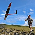
In Flight
I was able to attend the first flight which took place on the beautiful slope of Corps, south of Grenoble. The flight went perfectly, the CG was immediately correct. The geometry of the glider was entered on PredimRC (see Resources) beforehand to calculate the CG using a static margin of 2%.

Despite its 5m wingspan and 8.5kg, the glider seems light and agile in flight, responding like an F3F glider to the pilot’s commands, with the inertia and responsiveness of a larger and heavier model. The stability is excellent, the glider is like it’s on a rail in flight and is very precise.


Acceleration is excellent, and the energy retention in turns and other manoeuvres is incredible!
Elementary aerobatics are performed with ease and elegance. The six control surfaces allow the glider to slow down on landing, making you forget the size. The rigidity of the wings is satisfactory both in bending and in torsion.
Finally, the presence in the air of the glider with its large fuselage and the curve of the forward part is superb.
During another flight session, I was able to take the radio transmitter and fly this fantastic glider. The feeling on the sticks is excellent, a mix of lightness, precision and agility which is unusual on a glider of this size. A beautiful machine!
To finish, here are two videos you should be sure to watch. The first one is of the first flight in 2020 :
The second one is with an onboard camera which will allow you to appreciate the rigidity of the wing:
Conclusion
At the end of the day, it is safe to say this project has been a success, with all objectives met or exceeded. The satisfaction brought by this model makes the builders forget the hours spent in the workshop during the construction or in front of the computer for the design and the calculations. I can easily imagine that Joël Carlin is now impatiently waiting for his model, so that we can film or photograph the patrol flights of two 5m ASW-28s!

I hope that sharing these few lines on this project will have brought you some information and will give you the desire to launch yourself in this kind of construction!
Finally, a new French craftsman should emerge in the next few months with the ambition of marketing a glider of similar size using the series of profiles developed for this ASW-28 and working in close collaboration with Jean-Luc Foucher. And we’ll be happy to bring that news to you when it does! — Ed.

Specifications


©2023 Pierre RONDEL, Jean-Luc Foucher and Frédéric Hours
Resources
- GM Propellers on Facebook. — “High performance carbon propellers for hobby and competition…”
- HP-Textiles GmbH — “Since the company was founded in 2004, HP-Textiles GmbH has stood for the development and distribution of fibre composites…”
- JETI ENlink 2RS plus — “a device for increasing safety and reliability of radio controled models to the highest level … parallel connection of systems that are detached maximally leads to the significant increase in reliability…”
- Knauf Insulation — “Our mission is to challenge conventional thinking, create innovative insulation solutions that shape the way we live and build in the future…”
- Les Grands Planeurs RC (Large Scale RC Gliders) — The home of the spar calculation Excel spreadsheet created in 2003 by Jean-Luc Delort.
- PredimRC — “an aerodynamic analysis and simulation tool for aircraft models … for designers but also for pilots anxious to adjust correctly their device or to improve its behavior or performance…”
- Profili — “This new version can assist you in: · Searching for the right airfoil for your application · Creating new airfoils · Analyzing the airfoil aerodynamic…”
- TeXstreme — “spread tow reinforcements are a uniquely adaptable, safe and ultra light supportive solution for your carbon fiber composites…”
- ULMER Kunststoffteile GmbH — “We see ourselves as a competent solution partner in the development and production of high-quality and technically high-quality plastic products in vacuum thermoforming technology and hot forming…”
- XFLR5 — “an analysis tool for airfoils, wings and planes operating at low Reynolds Numbers…”
Read the next article in this issue, return to the previous article in this issue or go to the table of contents. A PDF version of this article, or the entire issue, is available upon request.